Dimensions and Cubes in ODI
In the realm of data analysis and business intelligence, time plays a crucial role in understanding trends, patterns, and performance over specific periods. Time dimensions and cubes are powerful constructs that facilitate the analysis and reporting of time-based data. These concepts are widely used in data warehousing and multidimensional analysis to provide insights into historical and current data trends.
| Source Tables | Staging Tables | Target Tables |
| SRC_YEAR | STG_YEAR | TIME |
| SRC_QUARTER | STG_QUARTER | TIME_ERRORS |
| SRC_MONTH | STG_MONTH | |
| SRC_DATE | STG_DATE |
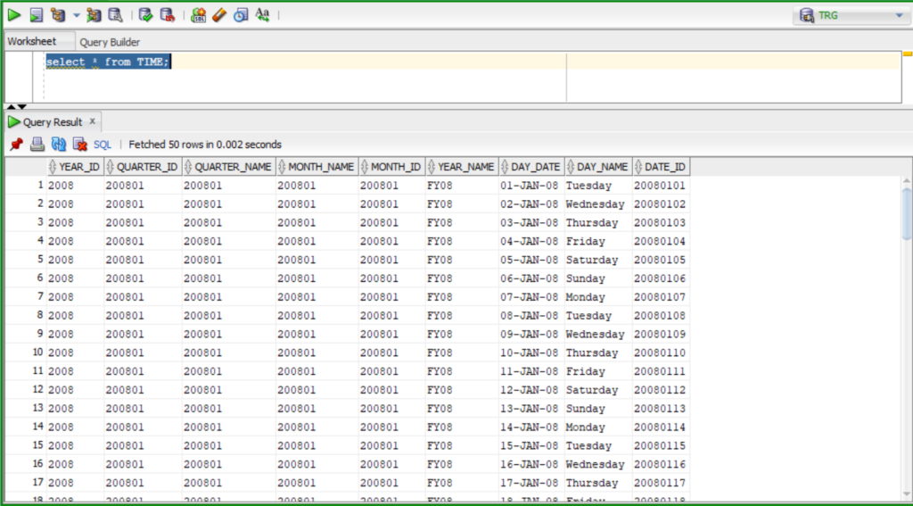
Time Table
In the new dimension creation form, click the Definition tab and enter TIME_DIM in the Name field. Under Binding, click set the data store for Dimension next to the Data store and Error Data store field.
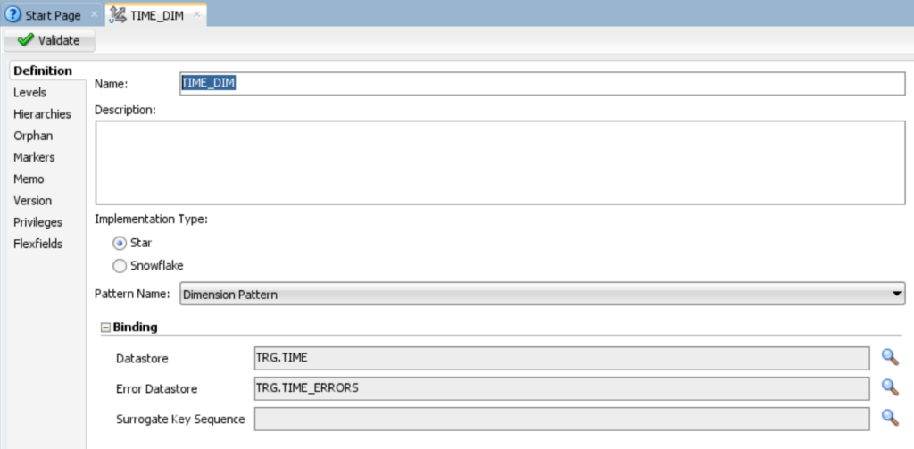
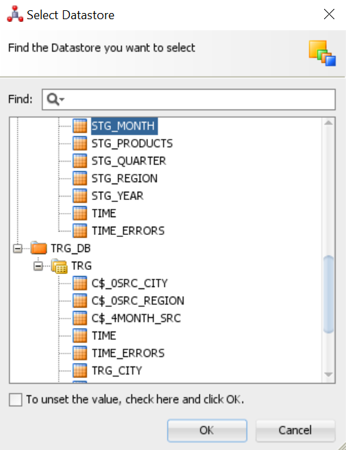
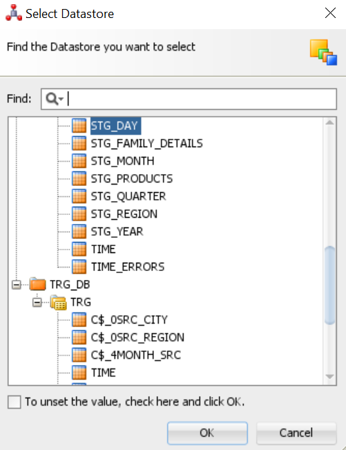
3. In the Select Data store dialog box, find the data store you want to select TIME .Under TRG_DB and click OK.
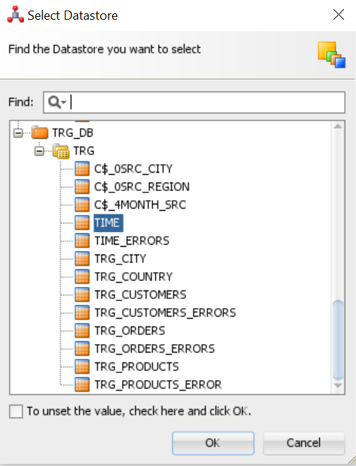
4. Repeat step 3 for TIME, Select TIME_ERRORS. Under C##_TRG and click OK.
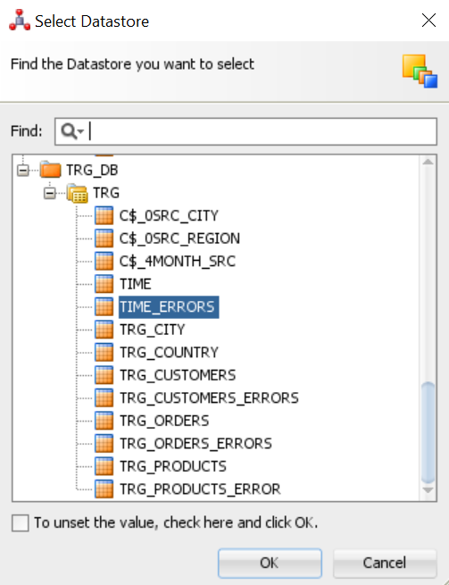
5.In the Binding pane, TIME. Appears in the Data store field. TIME_ERRORS appears in the Error Data store field.

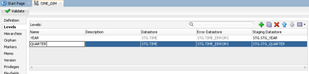
6.In the ODI menu bar, click Save.

2.3 Defining the Levels
In the following sections, you create levels for
•	Year.
•	Quarter.
•	Month.
•	Day.
Adding the Year Level
1.	Click the Levels tab.
2.	In the Levels table, click ( ). In the Name cell, change the name from Level1 to YEAR. In the Staging Data store cell, click the (…) button to open the Select Data store dialog box.
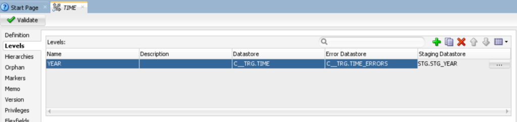
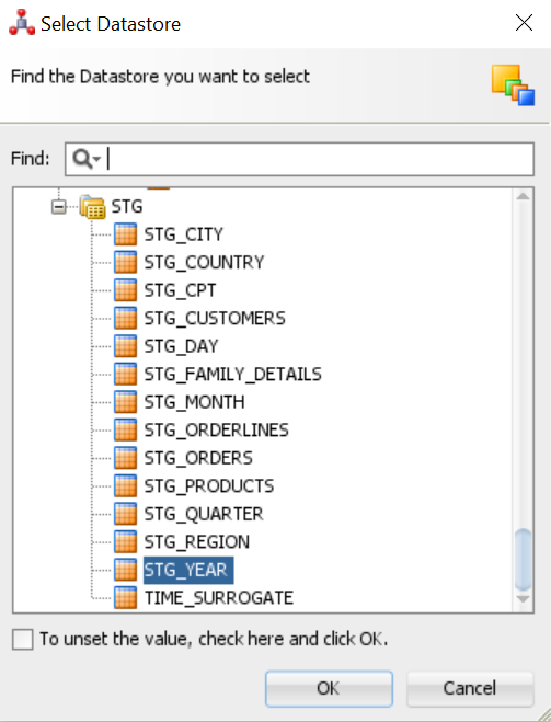
3. In the Staging data store select STG_YEAR and click OK.
4. In the Level Attributes table, click ( ), and add YEAR_ID and YEAR_NAME. Select the attribute, staging attribute and error attribute columns. If the data type of the column doesn’t appear, select data type from the menu. Set type2 settings to none.
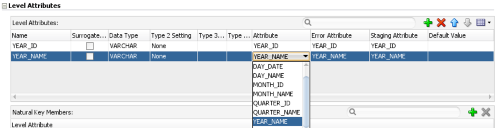
5. In the Natural Key Members table, click ( ), and then enter Natural_Key is YEAR_ID as shown in the given below figure.
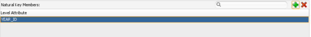
6.In the ODI menu bar, click Save.
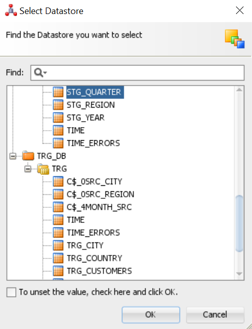
3.In the Staging data store select STG_QUARTER and click OK.
4.In the Level Attributes table, click ( ), and add QUARTER_ID and QUARTER_NAME. Select the attribute, staging attribute and error attribute columns. If the data type of the column doesn’t appear, select data type from the menu. Set type2 settings to none.

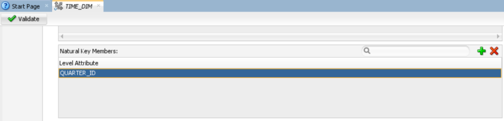
5. In the Natural Key Members table, click ( ), and then enter Natural_Key is QUARTER_ID as shown in the given below figure.
6. In the Parent References table, click ( ). In the Name cell, change the name from PARENTREF1 to QUARTER_PARENTREF. In the Parent Level cell, select YEAR.
In the Parent Level Reference Key Member table, confirm that the Parent Key Attribute cell shows Customers. TIME.YEAR_ID and that the Foreign Key Attribute and Foreign Key Staging Attribute cells show YEAR_ID.

7.In the ODI menu bar, click Save.

3.In the Staging data store select STG_MONTH and click OK.
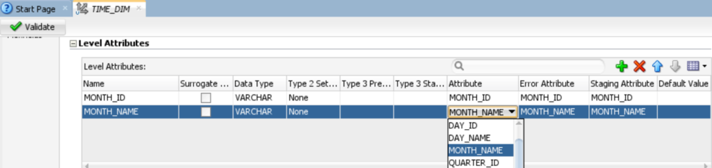
4.In the Level Attributes table, click ( ), and add MONTH_ID and MONTH_NAME. Select the attribute, staging attribute and error attribute columns. If the data type of the column doesn’t appear, select data type from the menu. Set type2 settings to none.
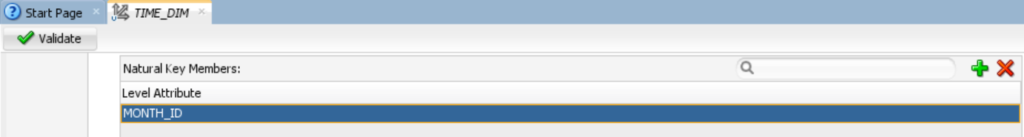
5.In the Natural Key Members table, click ( ), and then enter Natural_Key is MONTH_ID as shown in the given below figure.
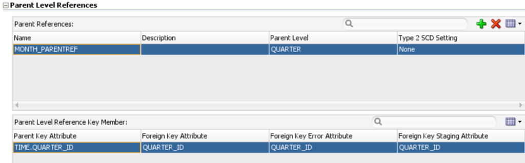
6.In the Parent References table, click ( ). In the Name cell, change the name from PARENTREF1 to MONTH_PARENTREF. In the Parent Level cell, select QUARTER.
In the Parent Level Reference Key Member table, confirm that the Parent Key Attribute cell shows Customers. TIME.QUARTER_ID and that the Foreign Key Attribute and Foreign Key Staging Attribute cells show QUARTER_ID.
7.In the ODI menu bar, click Save.
Adding the Day Level

3.In the Staging data store select STG_DAY and click OK.
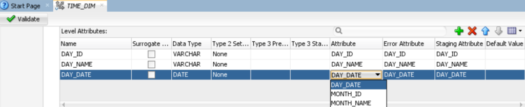
4.In the Level Attributes table, click ( ), and add DAY_ID, DAY_NAME and DAY_DATE. Select the attribute, staging attribute and error attribute columns. If the data type of the column doesn’t appear, select data type from the menu. Set type2 settings to none.
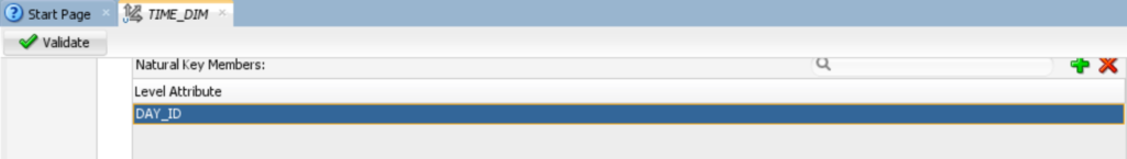
5.In the Natural Key Members table, click ( ), and then enter Natural_Key is DAY_ID as shown in the given below figure.
6.In the Parent References table, click ( ). In the Name cell, change the name from PARENTREF1 to DAY_PARENTREF. In the Parent Level cell, select MONTH.
In the Parent Level Reference Key Member table, confirm that the Parent Key Attribute cell shows Customers. TIME.MONTH_ID and that the Foreign Key Attribute and Foreign Key Staging Attribute cells show MONTH_ID.

7.In the ODI menu bar, click Save.

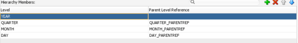
2. For hierarchy members, click ( ) and then add the following levels, leaving the default values in the Parent Level Reference column:
2.5
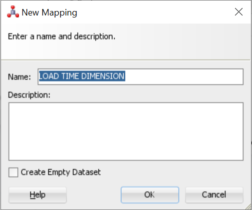
2.In the New Mapping dialog box, enter LOAD_TIME_DIMENSION in the Name field, deselect Create Empty Dataset, and click OK.
3. Map the following source attributes to the specified target attribute in TIME_DIM:
4. On the Designer tab, expand Models and C##SRC, then drag and drop SRC_YEAR, SRC_QUARTER, SRC_MONTHand SRC_DAY into the mapping area.
5. On the Designer tab, expand Dimensions and Cubes, then expand DIMENSIONAL MODEL, then expand DIMENSIONS, drag and drop TIME_DIM into the mapping area.
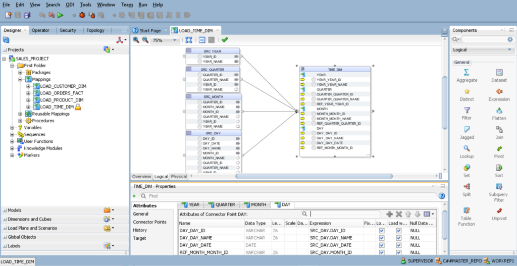
6. Create a connection between the following sources: – SRC_YEAR, SRC_QUARTER, SRC_MONTHand SRC_DAY, Target Tables to the TIME_DIM, in mapping area.
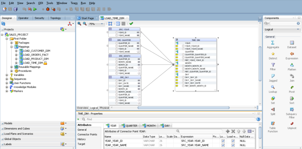
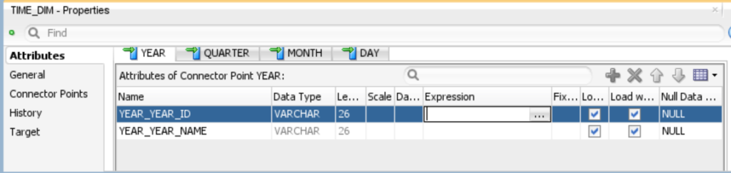
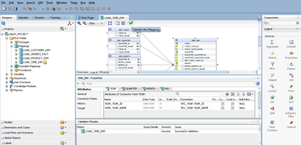
Click on TIME_DIM and select YEAR tab, you will find the below fields.
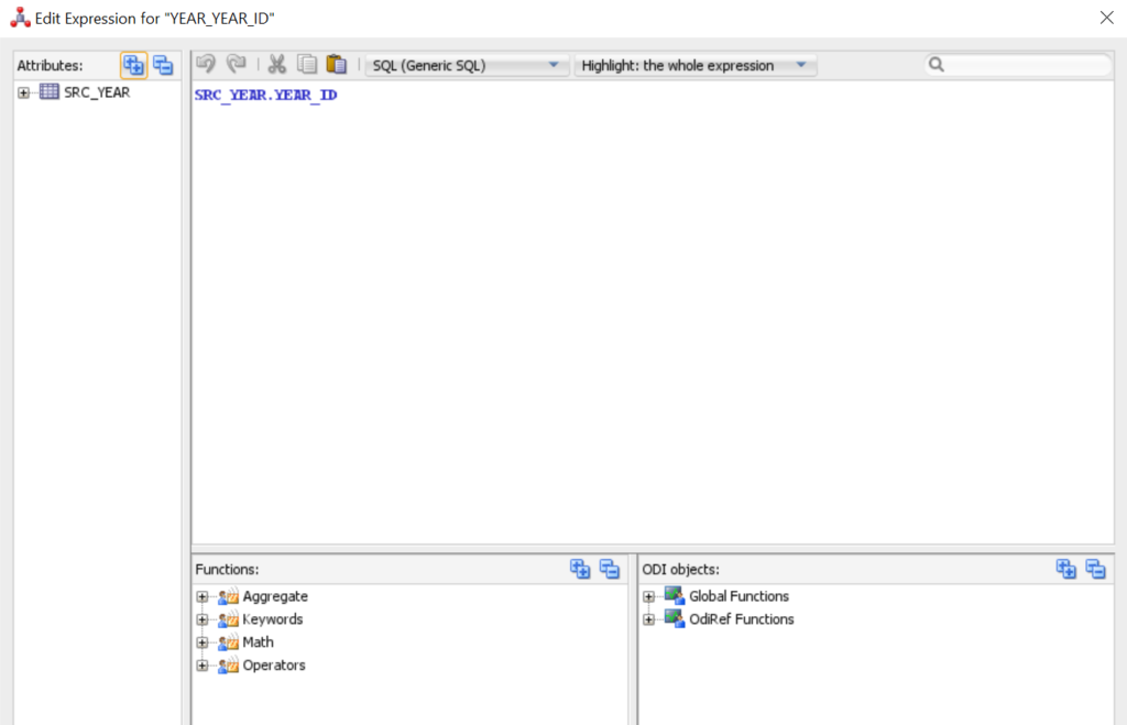
7.Map YEAR Attributes. Click on (…) and set the expression.
8.Select SRC_YEAR tab and choose respective attributes.
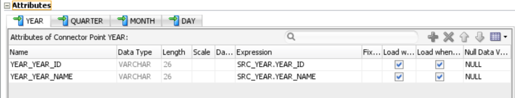
Note: – For QUARTER, MONTH, DAY attributes repeat the above steps. You will notice that the color of the columns have been changed to yellow after mapping the expression.
9. Click the Physical tab and review the physical mapping.
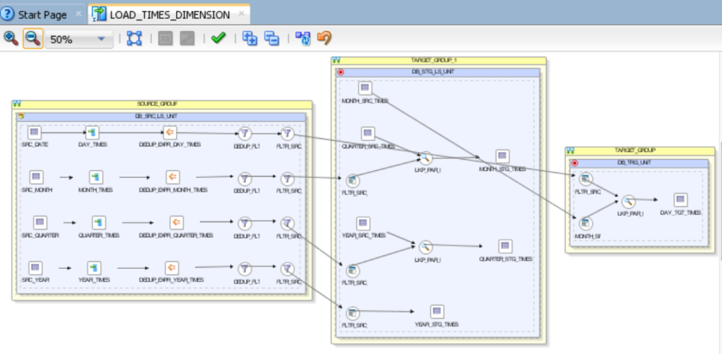
10.Click Validate the Mapping, click Save in the ODI menu bar, and then close the Load TIME_DIM Dimension tab.
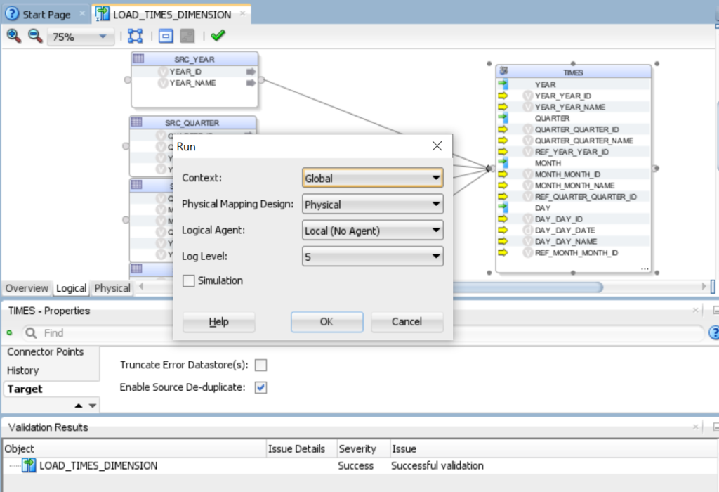
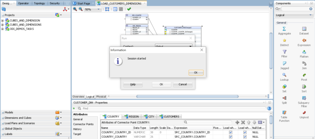
11. Execute the mapping LOAD_TIME_DIMENSION.
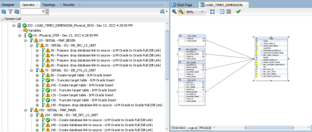
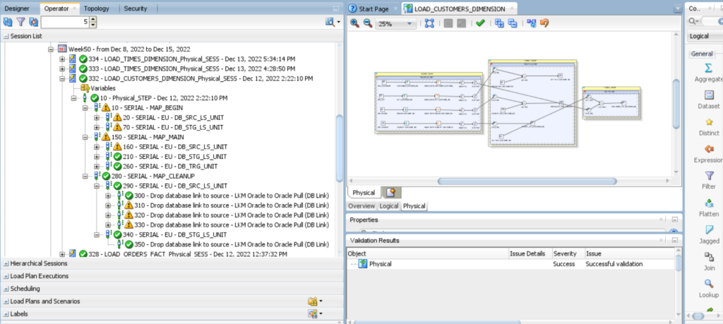
12.Check result of session task status of the session list in Operator Tab.
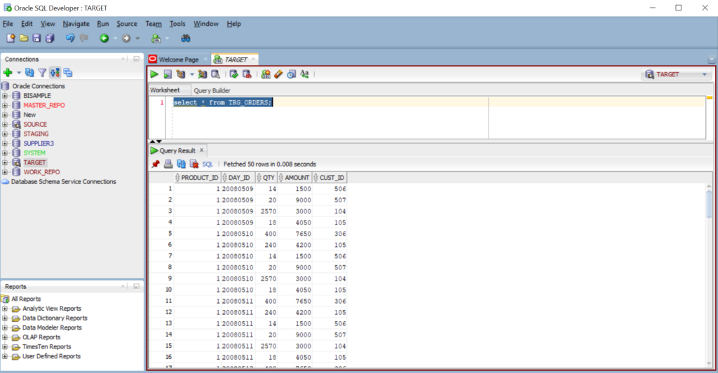
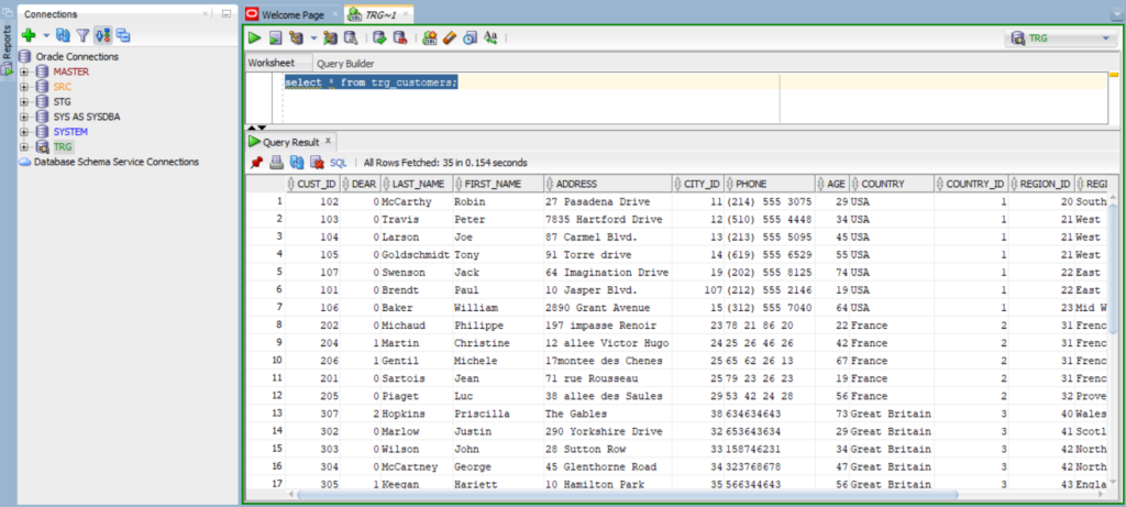
13.Now you have to view the data in database TRG.
| Source Tables | Staging Tables | Target Tables |
| SRC_FAMILY_DETAILS | STG_FAMILY_DETAILS | TRG_PRODUCT |
| SRC_PRODUCT | STG_PRODUCT | TRG_PRODUCT_ERRORS |
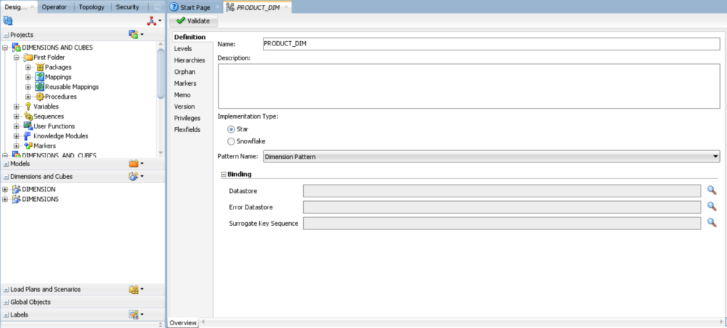
2 . In the new dimension creation form, click the Definition tab and enter PRODUCT_DIM in the Name field. Under Binding, click set the data store for Dimension next to the Data store and Error Data store field.
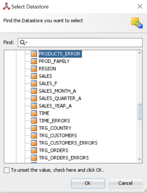
3.In the Select Data store dialog box, find the data store you want to select TRG_PRODUCTS. Under C##_TRG and click OK.
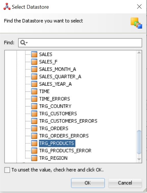
4. Repeat step 3 for TRG_PRODUCTS_ERRORS, Select TRG_ PRODUCTS_ERRORS. Under C##_TRG and click OK.
5.In the Binding pane, TRG_PRODUCTS Appears in the Data store field. TRG_ PRODUCTS_ERRORS appears in the Error Data store field.
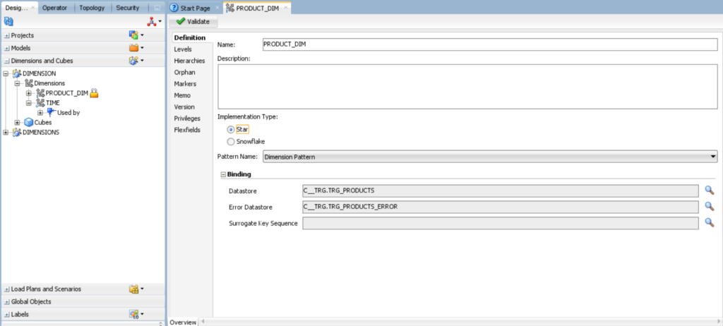
6.In the ODI menu bar, click Save.
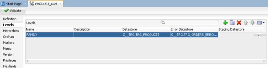
3.3 Defining the Levels
In the following sections, you create levels for
•	Family.
•	Product.
Adding the Family Level
1.	Click the Levels tab.
2.	In the Levels table, click ( ). In the Name cell, change the name from Level1 to FAMILY. In the Staging Data store cell, click the (…) button to open the Select Data store dialog box.

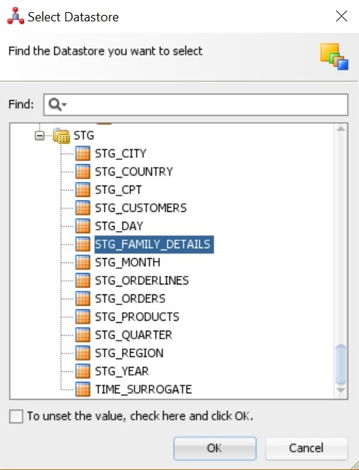
3.In the Staging data store Select STG_FAMILY_DETAILS and click OK.
4.In the Level Attributes table, click ( ), and add FAMILY_ID and FAMILY_NAME select the attribute, staging attribute and error attribute columns. If the data type of the column doesn’t appear, select data type from the menu. Set type2 settings to none.
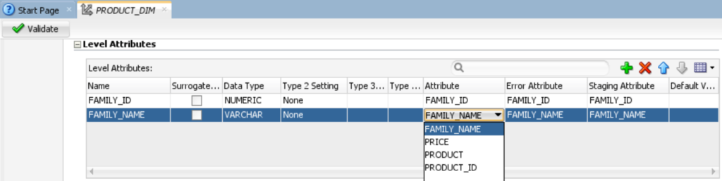
5.In the Natural Key Members table, click ( ), and then enter Natural_Key is FAMILY_ID as shown in the given below figure.

6.In the ODI menu bar, click Save.
Adding the Product Level
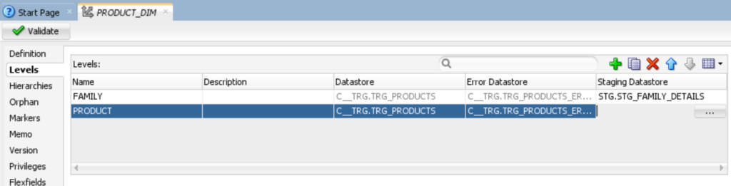
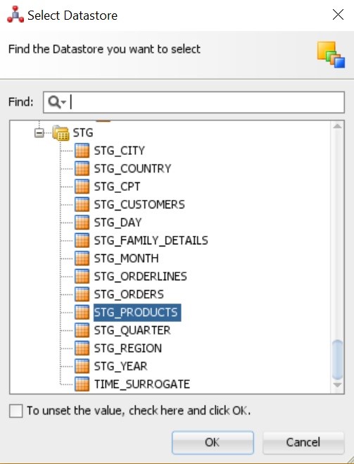
3.In the Staging data store select STG_PRODUCTS and click OK.
4.In the Level Attributes table, click ( ), and add PRODUCT_ID, PRODUCT and PRICE. Select the attribute, staging attribute and error attribute columns. If the data type of the column doesn’t appear, select data type from the menu. Set type2 settings to none.
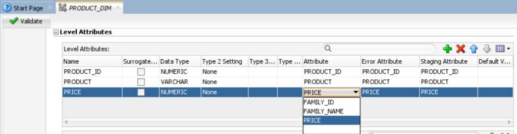
5.In the Natural Key Members table, click ( ), and then enter Natural_Key is PRODUCT_ID as shown in the given below figure.

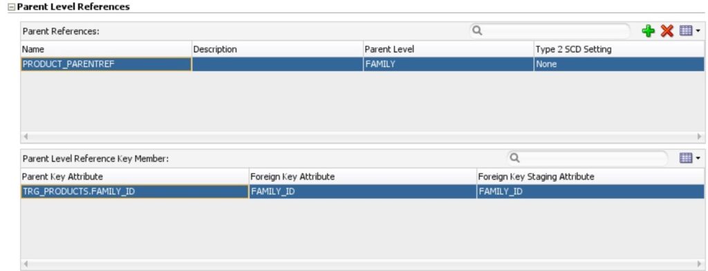
6.In the Parent References table, click ( ) Add. In the Name cell, change the name from PARENTREF1 to PRODUCT_PARENTREF. In the parent level cell, select FAMILY.
In the Parent Level Reference Key Member table, confirm that the Parent Key Attribute cell shows TRG_PRODUCTS.FAMILY_ID and that the Foreign Key Attribute and Foreign Key Staging Attribute cells show FAMILY_ID.
7.In the ODI menu bar, click Save.
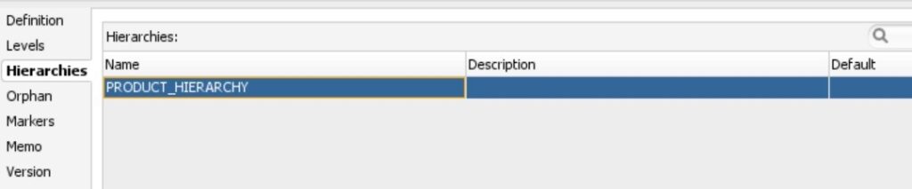
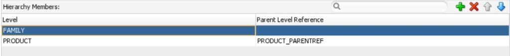
2.For hierarchy members, click ( )Add and then add the following levels, leaving the default values in the Parent Level Reference column:
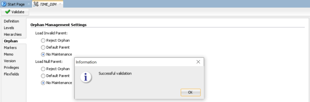
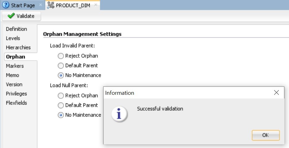
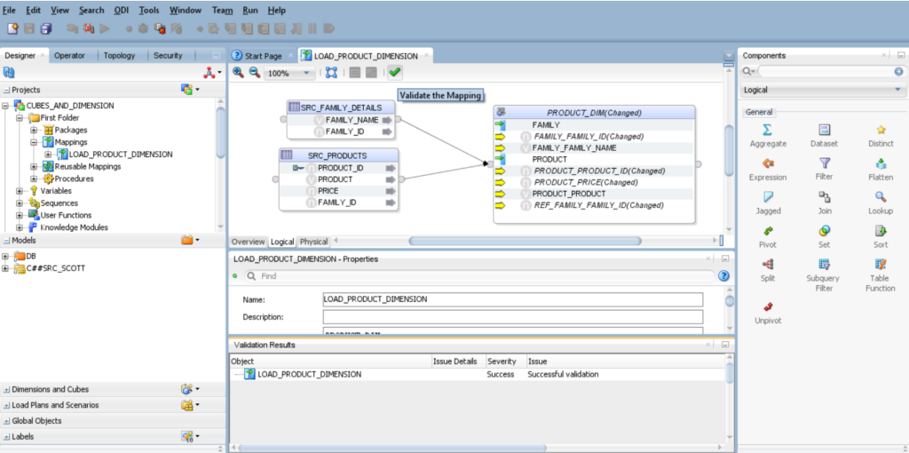
3.In the ODI menu bar, click Save, and then click Validate. When the “Successful Validation” message appears, click OK and close the PRODUCT_DIMENSION tab in your workspace.

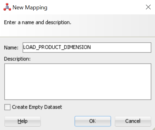
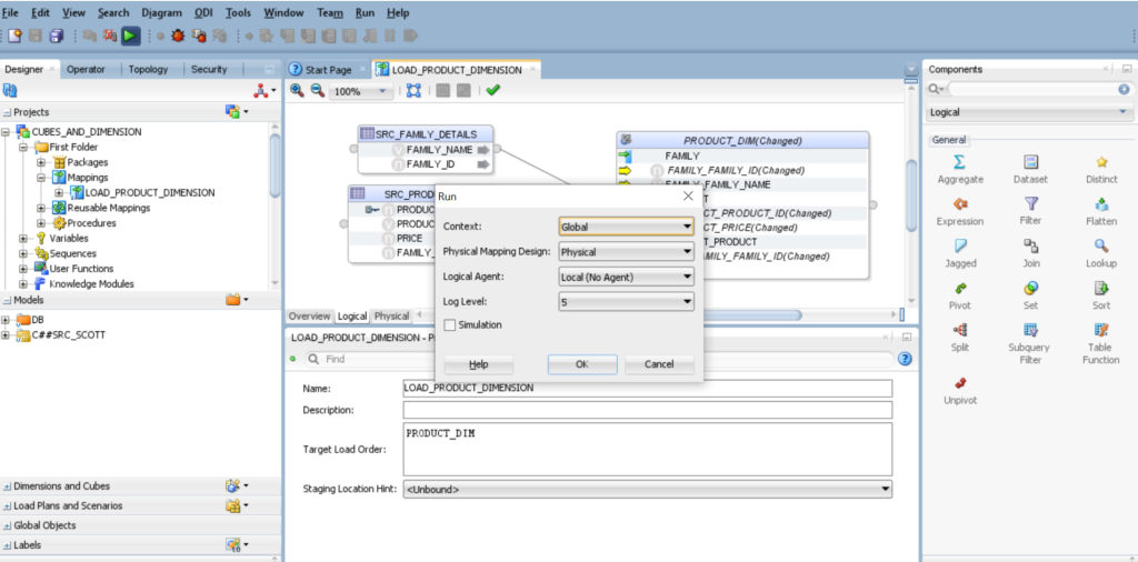
2.In the New Mapping dialog box, enter LOAD_PRODUCT_DOMENSION in the Name field, deselect Create Empty Dataset, and click OK.
3. Map the following source attributes to the specified target attribute in PRODUCT_DIM:
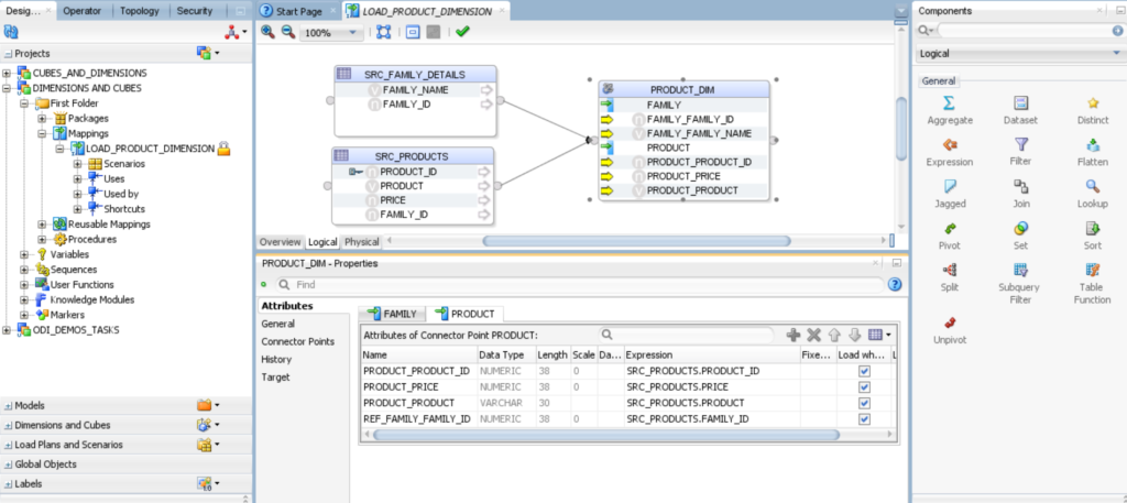
4. On the Designer tab, expand Models and C##SRC, then drag and drop SRC_FAMILY_DETAILS and SRC_PRODUCTS into the mapping area.
5. On the Designer tab, expand Dimensions and Cubes, then expand DIMENSIONAL MODEL, then expand DIMENSIONS, drag drop PRODUCT_DIM into the mapping area.
6. Create a connection between following source: – SRC_FAMILY_DETAILS, SRC_PRODUCT to the PRODUCT_DIM, in mapping Area.
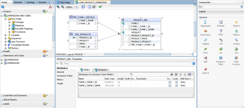
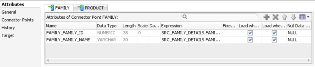
Click on PRODUCT_DIM and select FAMILY tab, you will find the below fields.
Click on PRODUCT_DIM and select FAMILY tab, you will find the below fields.
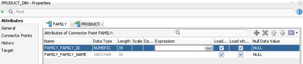
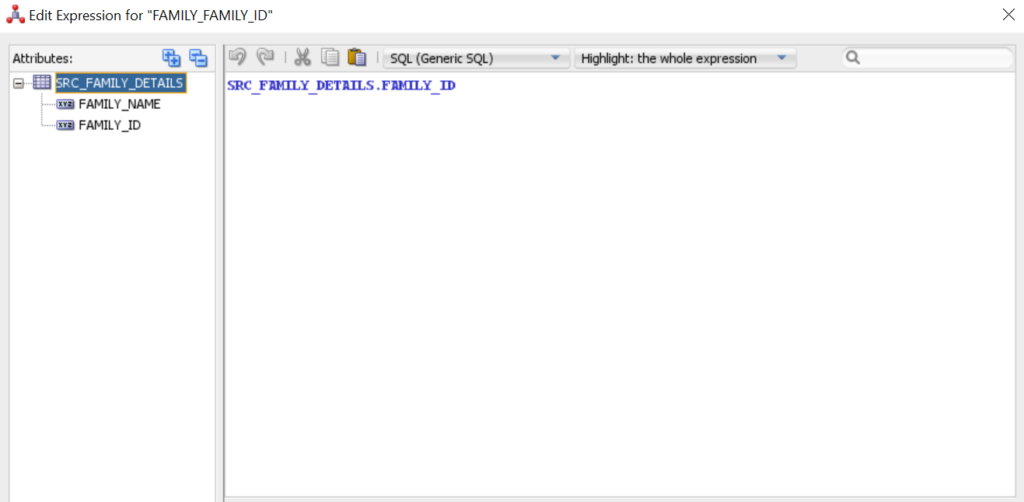
8.Select SRC_FAMILY_DETAILS tab and choose respective attributes.
NOTE :- For PRODUCT attributes repeat the above steps. You will notice that the color of the columns have been changed to yellow after mapping the expression.
9.Click the Physical tab and review the physical mapping
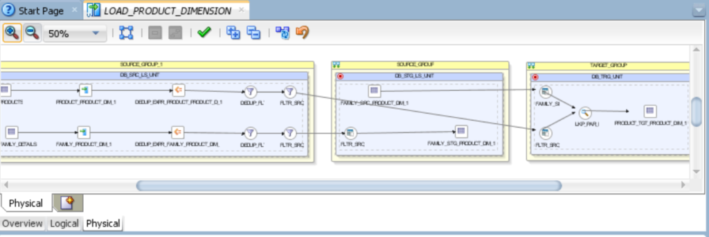
10.Click Validate the Mapping, click Save in the ODI menu bar, and then close the Load PRODUCT_DIM Dimension tab.
11.Execute the mapping LOAD_PRODUCT_DIMENSION.
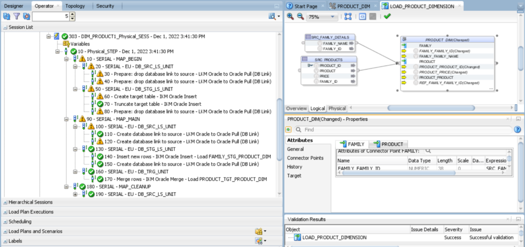
12.Navigate to Operator Tab and monitor the load.
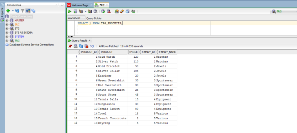
13.Now you have to view the data in database TRG.
| Source Tables | Staging Tables | Target Tables |
| SRC_COUNTRY | STG_COUNTRY | TRG_CUSTOMERS |
| SRC_REGION | STG_REGION | TRG_CUSTOMERS_ERRORS |
| SRC_CITY | STG_CITY | |
| SRC_CUSTMER | STG_CUSTMER |

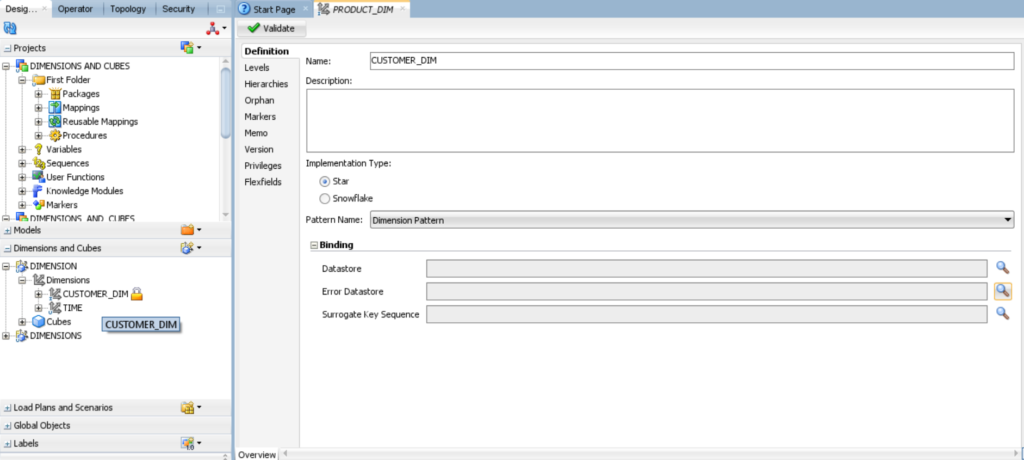
2.In the new dimension creation form, click the Definition tab and enter CUSTOMER_DIM in the Name field. Under Binding, click set the data store for Dimension next to the Data store and Error Data store field.
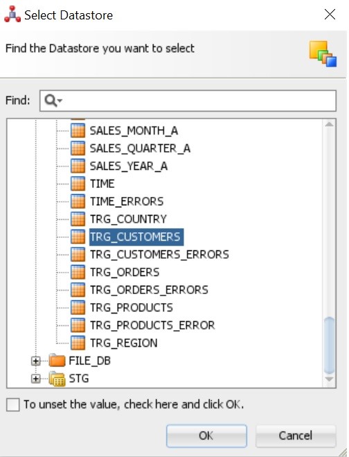
3.In the Select Data store dialog box, find the data store you want to select TRG_CUSTOMER. Under C##_TRG and click OK.
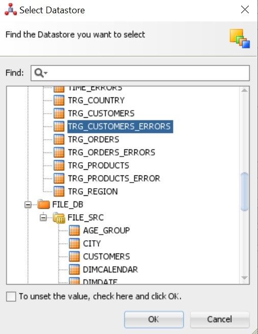
4. Repeat step 3 for TRG_CUSTOMERS_ERRORS, Select TRG_CUSTOMERS_ERRORS. Under C##_TRG and click OK.
1.In the Binding pane, TRG_CUSTOMERS Appears in the Data store field. TRG_CUSTOMERS_ERRORS appears in the Error Data store field.
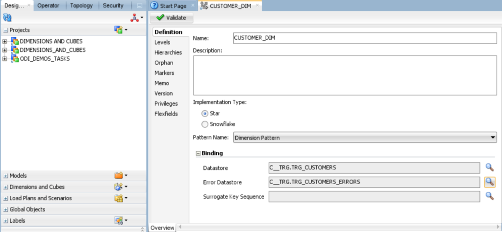
6.In the ODI menu bar, click Save.
In the following sections, you create levels for
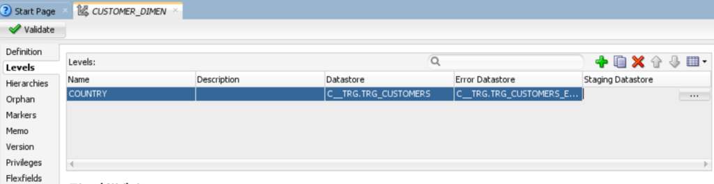
3. In the Staging data store select STG_COUNTRY and click OK.
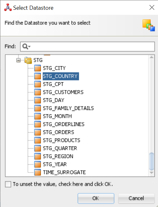
4.In the Level Attributes table, click ( ), and add COUNTRY_ID and COUNTRY. Select the attribute, staging attribute and error attribute columns. If the data type of the column doesn’t appear, select data type from the menu. Set type2 settings to none.
5.In the Natural Key Members table, click ( ), and then enter Natural_Key is COUNTRY_ID as shown in the given below figure.

6.In the ODI menu bar, click Save.
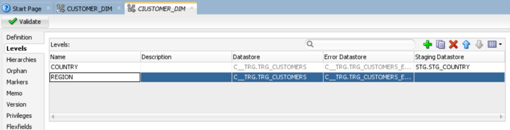
3.In the Staging data store select STG_REGION and click OK.
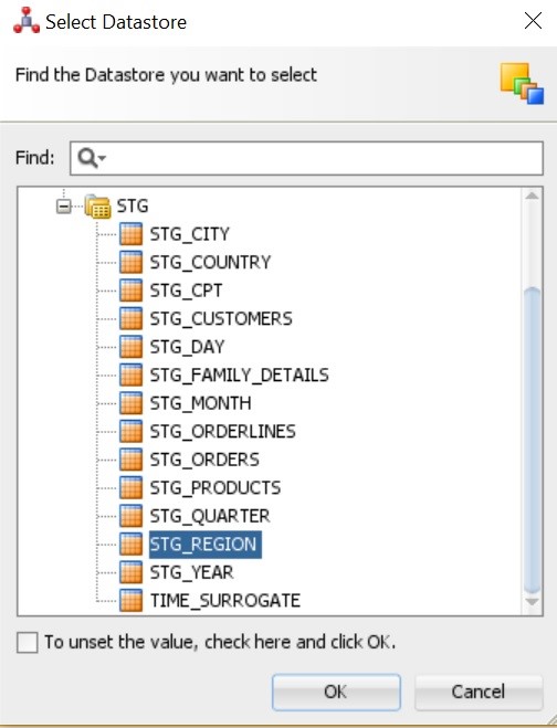
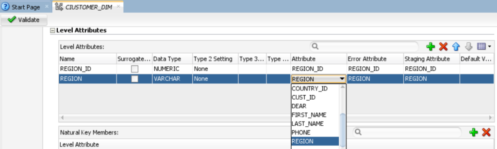
4. In the Level Attributes table, click ( ), and add REGION_ID and REGION. Select the attribute, staging attribute and error attribute columns. If the data type of the column doesn’t appear, select data type from the menu. Set type2 settings to none.
5.In the Natural Key Members table, click ( ), and then enter Natural_Key is REGION_ID as shown in the given below figure.
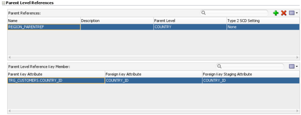
6.In the Parent References table, click ( ). In the Name cell, change the name from PARENTREF1 to REGION_PARENTREF. In the Parent Level cell, select COUNTRY.
In the Parent Level Reference Key Member table, confirm that the Parent Key Attribute cell shows Customers. TRG_CUSTOMERS.COUNTRY_ID and that the Foreign Key Attribute and Foreign Key Staging Attribute cells show COUNTRY_ID.
7. In the ODI menu bar, click Save.
3.In the Staging data store select STG_CITY and click OK.
4.In the Level Attributes table, click ( ), and add CITY_ID and CITY. Select the attribute, staging attribute and error attribute columns. If the data type of the column doesn’t appear, select data type from the menu. Set type2 settings to none.
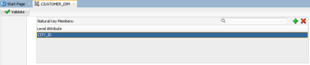
5.In the Natural Key Members table, click ( ), and then enter Natural_Key is CITY_ID as shown in the given below figure.
6.In the Parent References table, click ( ). In the Name cell, change the name from PARENTREF1 to CITY_PARENTREF. In the Parent Level cell, select REGION.
In the Parent Level Reference Key Member table, confirm that the Parent Key Attribute cell shows TRG_CUSTOMERS.REGION_ID and that the Foreign Key Attribute and Foreign Key Staging Attribute cells show REGION_ID.

7.In the ODI menu bar, click Save.

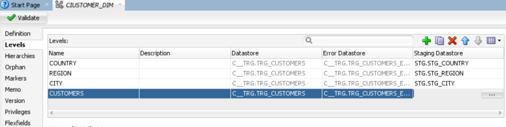
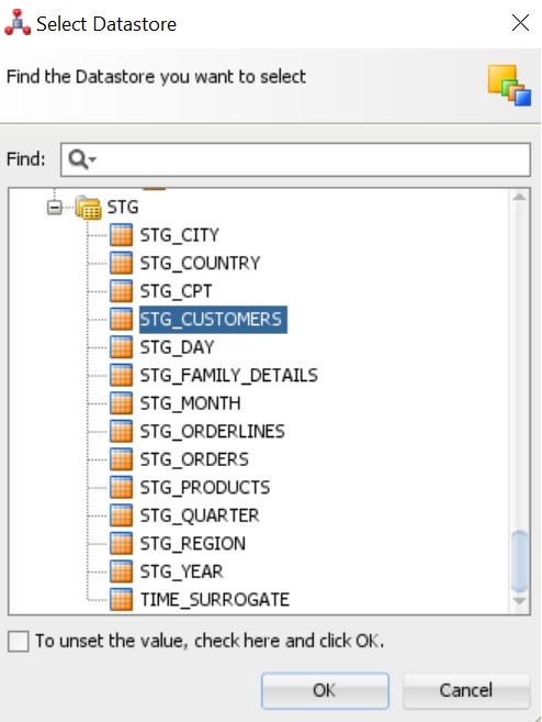
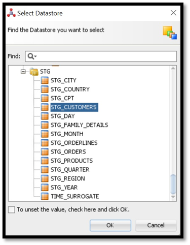
3.In the Staging data store Select STG_CUSTOMERS and click OK.
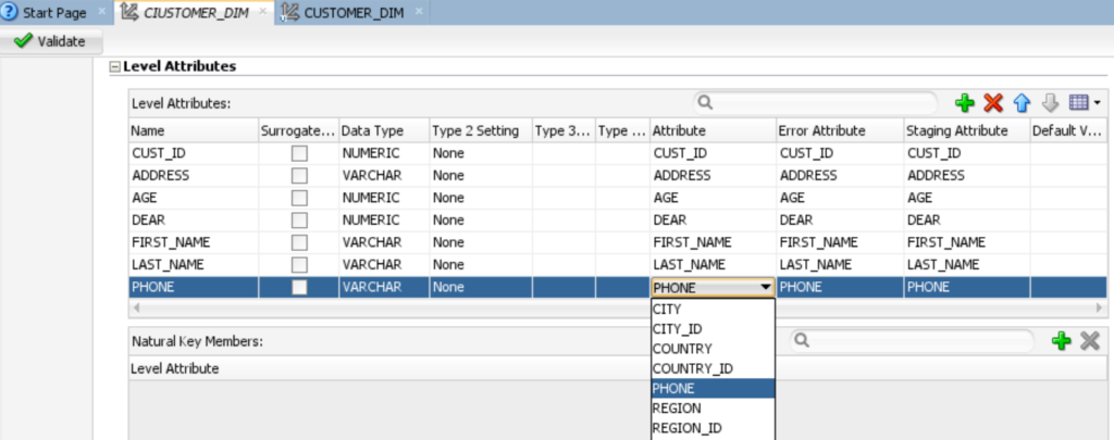
4.In the Level Attributes table, click ( ), and add CUST_ID and ADDRESS, AGE, DEAR, FIRST_NAME, LAST_NAME and PHONE. Select the attribute, staging attribute and error attribute columns. If the data type of the column doesn’t appear, select data type from the menu. Set type2 settings to none.

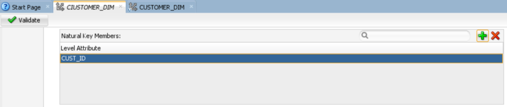
5.In the Natural Key Members table, click ( ), and then enter Natural_Key is CUST_ID as shown in the given below figure.

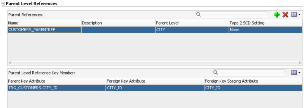
6.In the Parent References table, click ( ). In the Name cell, change the name from PARENTREF1 to CUSTOMERS_PARENTREF. In the Parent Level cell, select CITY.
In the Parent Level Reference Key Member table, confirm that the Parent Key Attribute cell shows TRG_CUSTOMERS.CITY_ID and that the Foreign Key Attribute and Foreign Key Staging Attribute cells show CITY_ID.
7.In the ODI menu bar, click Save.
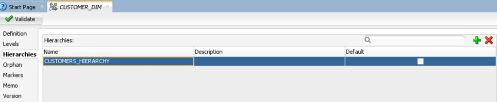
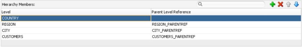
2.For hierarchy members, click ( ) and then add the following levels, leaving the default values in the Parent Level Reference column:
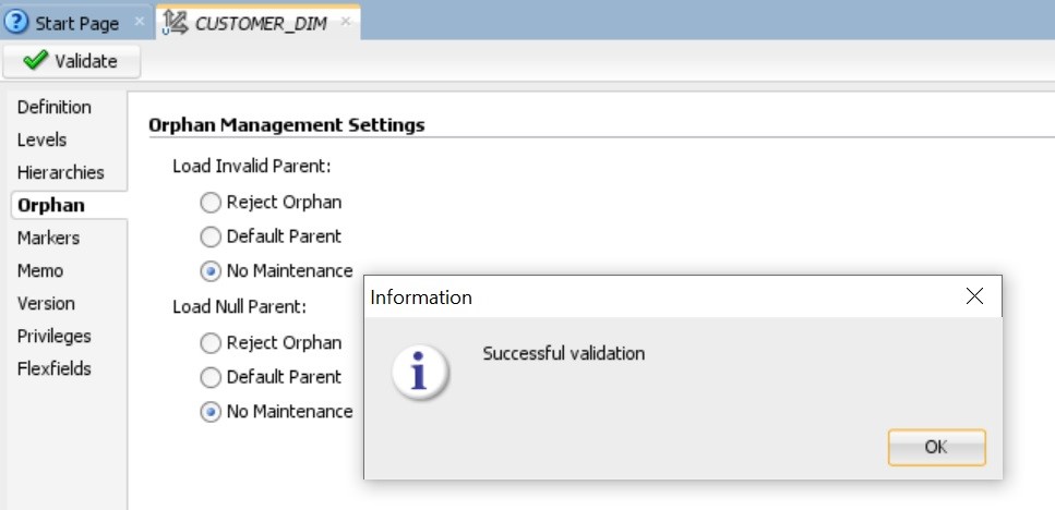
3.In the ODI menu bar, click Save, and then click Validate. When the “Successful Validation” message appears, click OK and close the CUSTOMERS_DIMENSION tab in your workspace.
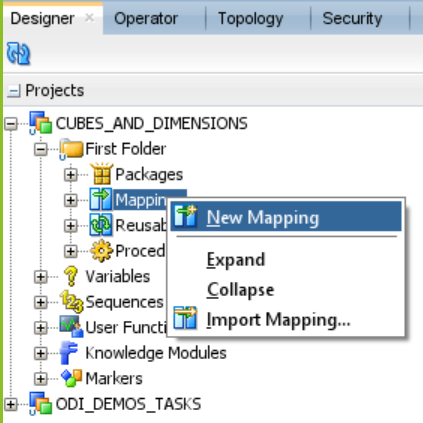
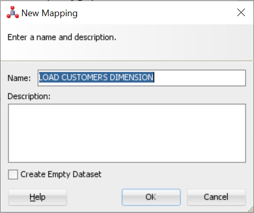
On the Designer tab, expand Projects, right-click Mappings and select New Mapping.

2.In the New Mapping dialog box, enter LOAD_CUSTOMERS_DIMENSION in the Name field, deselect Create Empty Dataset, and click OK.
3.Map the following source attributes to the specified target attribute in CUSTOMER_DIM:
4.On the Designer tab, expand Models and C##SRC, then drag and drop SRC_COUNTRY, SRC_REGION, SRC_CITY and SRC_CUSTOMER into the mapping area.
5.On the Designer tab, expand Dimensions and Cubes, then expand DIMENSIONAL MODEL, then expand DIMENSIONS, drag and drop CUSTOMER_DIM into the mapping area.
6. Create a connection between the following sources: – SRC_COUNTRY, SRC_REGION, SRC_CITY and SRC_CUSTOMER, Target Tables to the CUSTOMER_DIM, in mapping area.
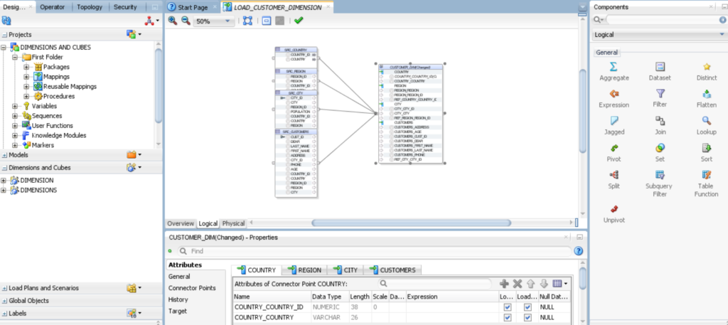
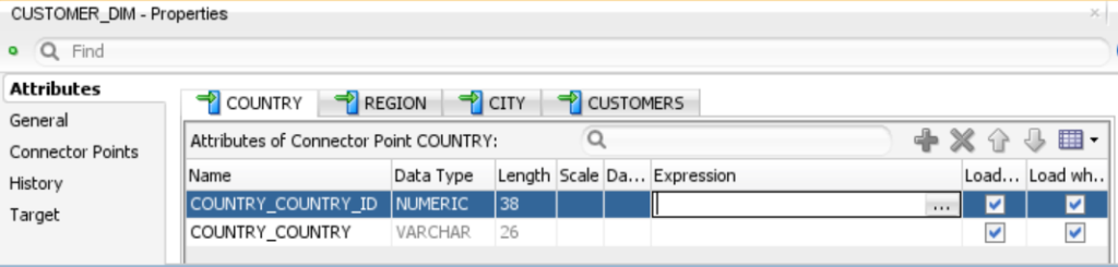
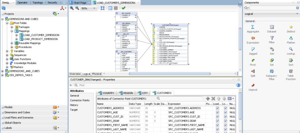
7.Clicking on CUSTOMER_DIM you can get attributes of connector point. COUNTRY, REGION, CITY and CUSTOMER.
Click on CUSTOMER_DIM and select COUNTRY tab, you will find the below fields.
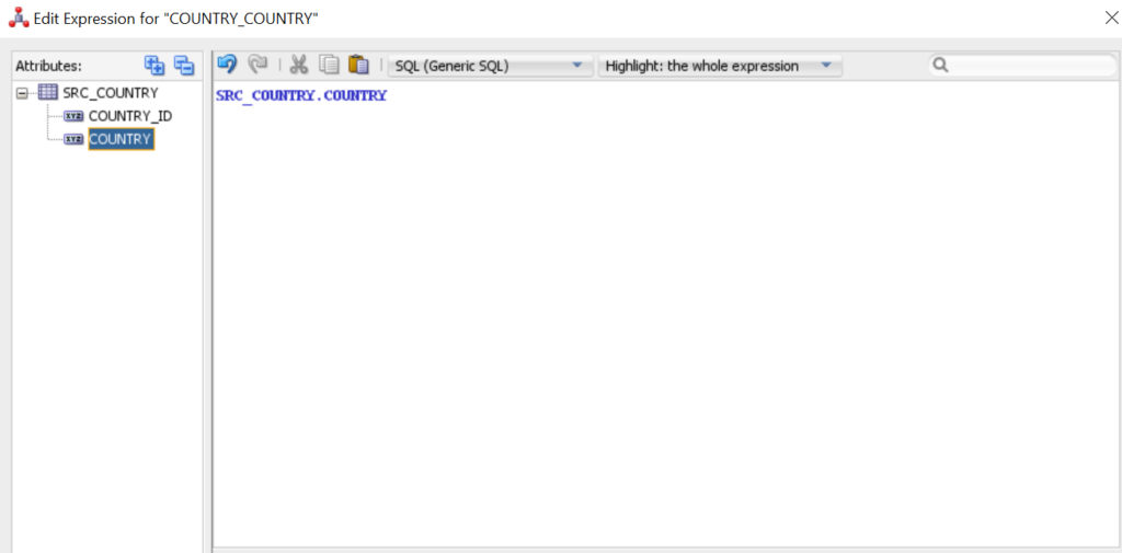
8.Map COUNTRY Attributes. Click on (…) and set the expression.
9.Select SRC_COUNTRY tab and choose respective attributes.
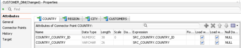
NOTE: – For REGION, CITY, CUSTOMERS attributes repeat the above steps. You will notice that the color of the columns have been changed to yellow after mapping the expression.
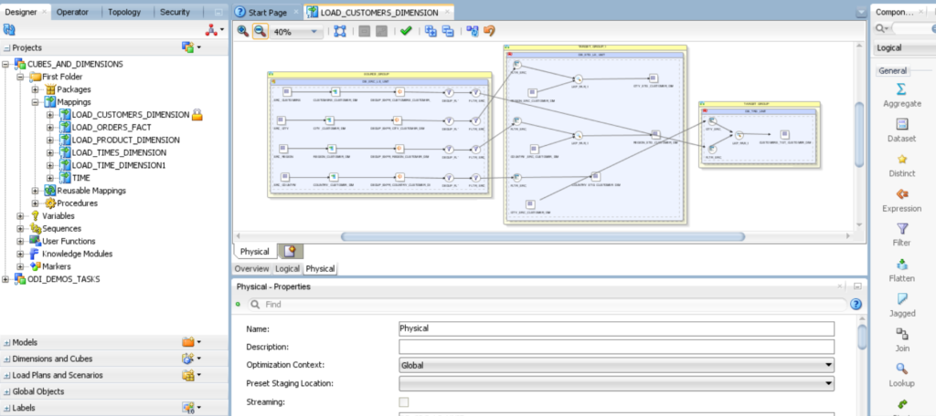
10.Click the Physical tab and review the physical mapping.
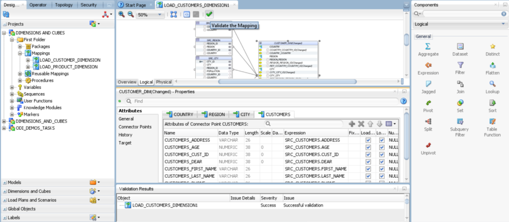
11.Click Validate the Mapping, click Save in the ODI menu bar, and then close the Load CUSTOMER_DIM Dimension tab.
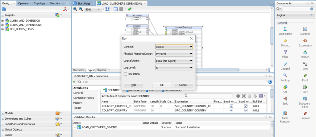
12.Execute the mapping LOAD_CUSTOMER_DIMENSION.
13.Check result of session task status of the session list in Operator Tab.
14.Now you have to view the data in database TRG.
| Source Tables | Target Tables |
| SRC_ORDERS | TRG_ORDERS |
| TRG_ORDERS_ERRORS |
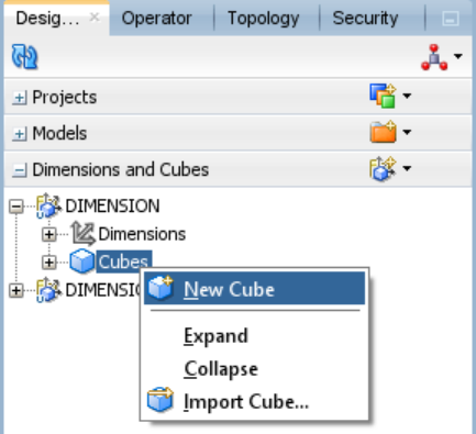
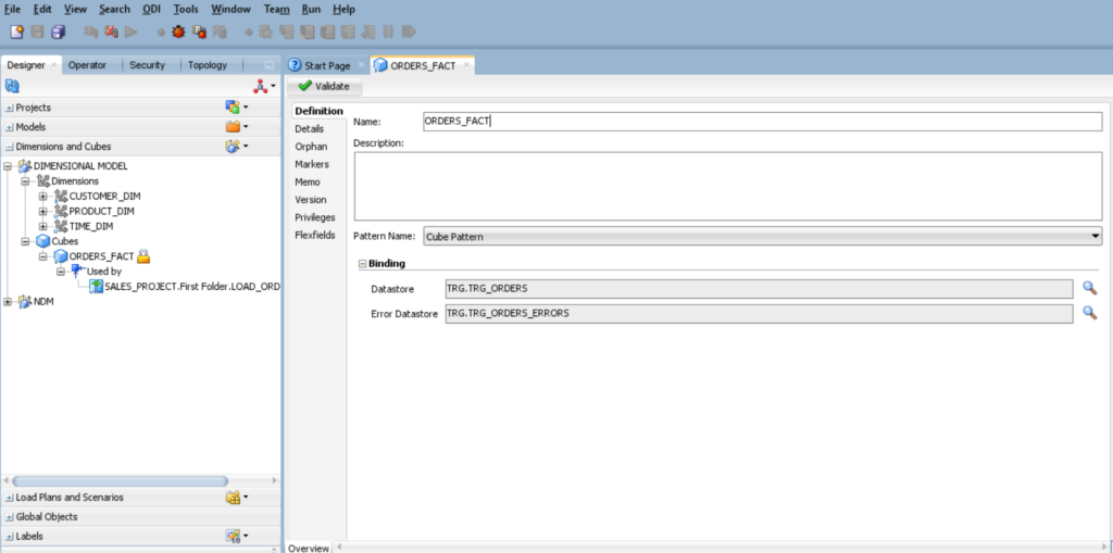
2. In the new cube creation form, click the definition tab and enter ORDERS_FACT in the Name field. Under binding, click set the data store for Cube next to the data store and Error data store field.
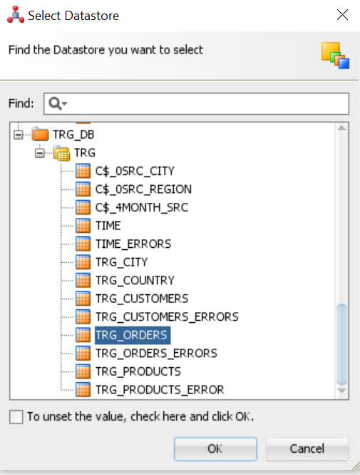
3.In the select data store dialog box, find the data store you want to select TRG_ORDERS. Under C##_TRG and click OK
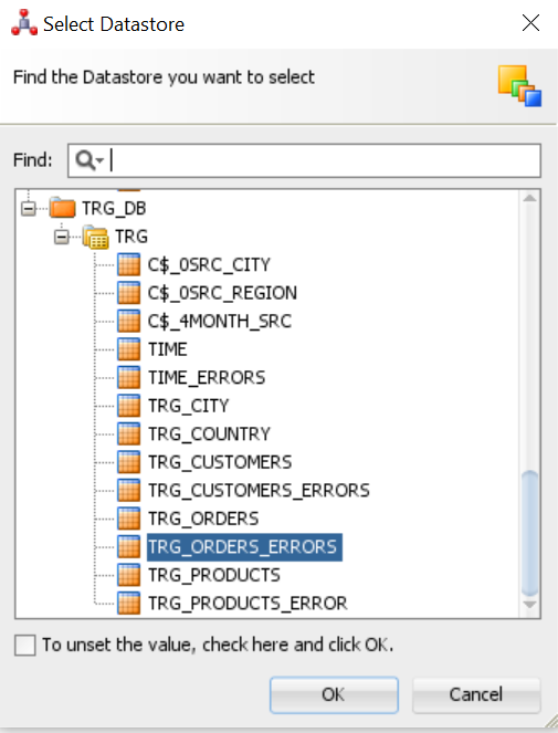
4.Repeat step 3 for TRG_ORDERS_ERRORS, Select TRG_ORDERS_ERRORS. Under C##_TRG and click OK.
5.In the Binding pane, TRG_ORDERS Appears in the Data store field. TRG_ORDERS_ERRORS appears in the Error Data store field.
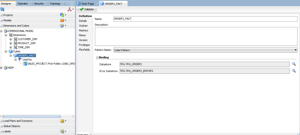
6. In the ODI menu bar, click Save.
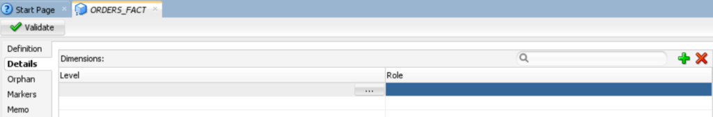
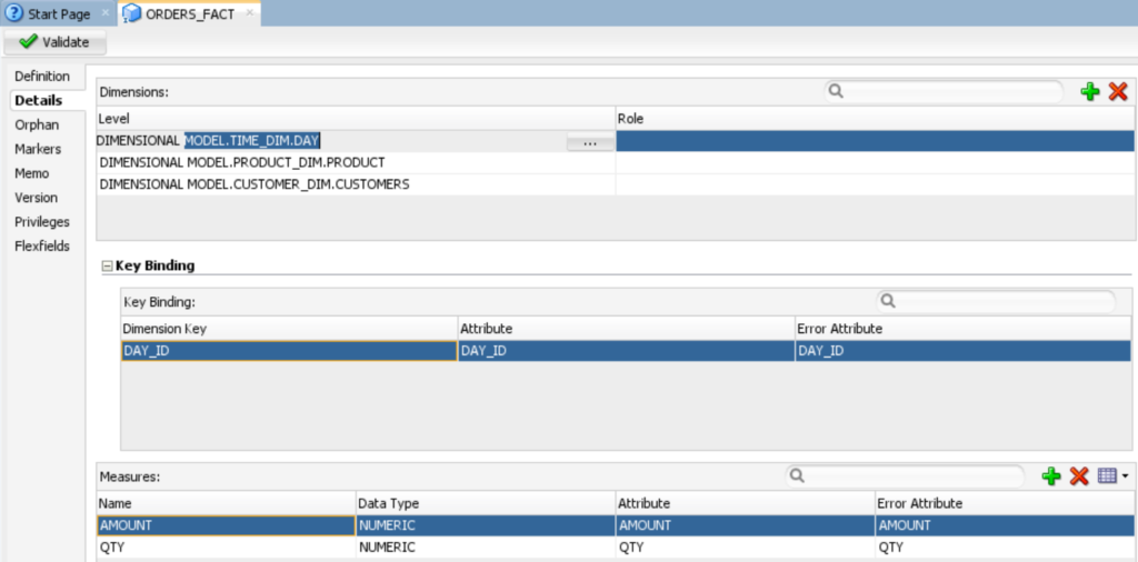
7.Click the details tab. In the dimensions table, click ( ) and then click the (…) button in the empty field.
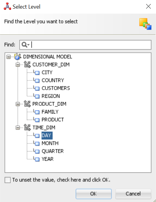
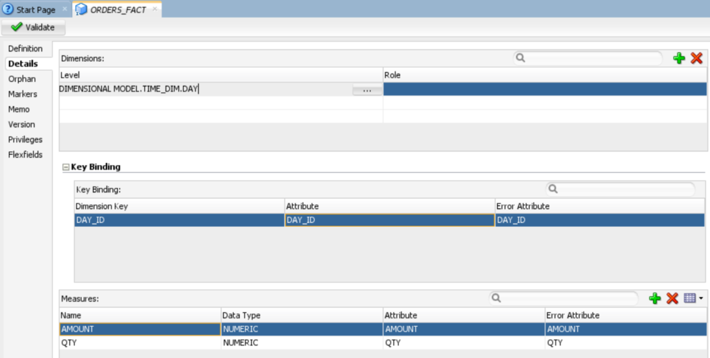
8.In the Select Level dialog box, under TIME_DIM, select Day, and click OK
9. In the Key Binding table, for the DAY_ID row, select DAY_ID in the Attribute and error attribute field.

Your Measures section should like the following image.
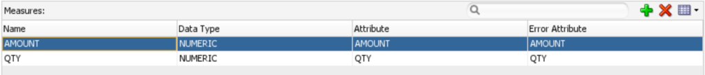
10.In the above table, you would fill in the specific name, data type, attribute, and error attribute for each measure in the time dimension.
NOTE: The time dimension steps have been completed. Moving forward, the same time dimension steps will be applied to the remaining PRODUCT_DIM and CUSTOMER_DIM.

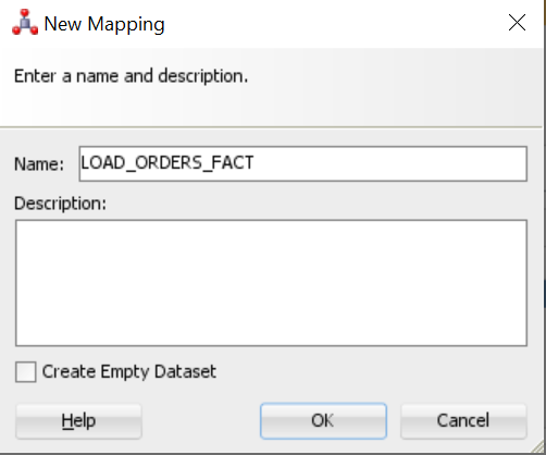
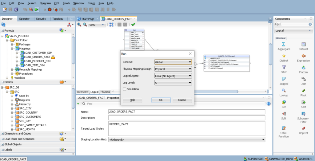
2.In the New Mapping dialog box, enter LOAD_ORDERS_FACT in the Name field, deselect Create Empty Dataset, and click OK.
3. Map the following source attributes to the specified target attribute in ORDERS_FACT:
4.On the Designer tab, expand Models and C##SRC, then drag and drop TIME, SRC_ORDERS, SRC_CUSTOMERS and SRC_PRODUCTS into the mapping area.
5. On the Designer tab, expand Dimensions and Cubes, then expand DIMENSIONAL MODEL, then expand DIMENSIONS, drag and drop ORDERS_FACT into the mapping area.
6.Create a connection between the following sources: – TIME, SRC_PRODUCTS, SRC_ORDERSand SRC_CUSTOMER, Target Cube to the ORDERS_FACT, in mapping area.
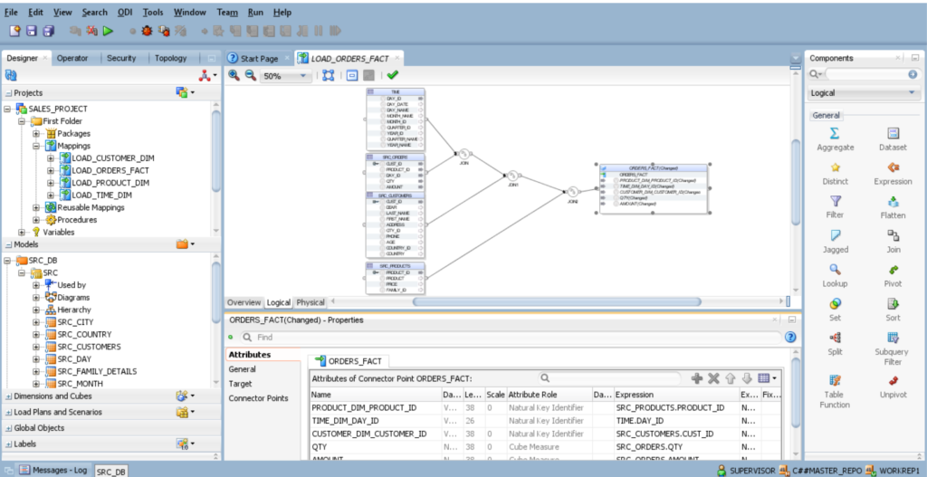
TIME, SRC_ORDERS, SRC_CUSTOMERS and SRC_PRODUCT.
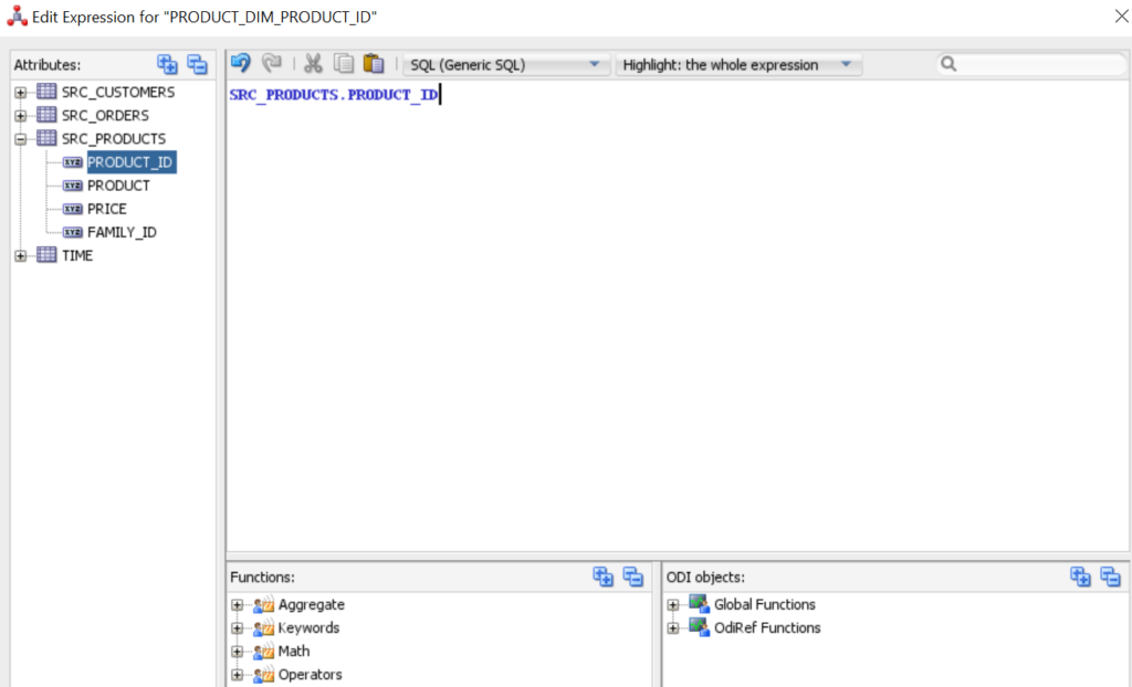
Click on ORDERS_FACT Cube and select ORDERS_FACT tab, you will find the below fields.
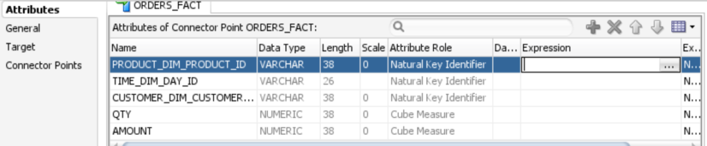
9.Select ORDERS_FACT tab and choose respective attributes.

NOTE: – For ORDERS_FACT You will notice that the colors of the columns have been changed to grey or yellow after mapping the expression.
10.Click the Physical tab and review the physical mapping.
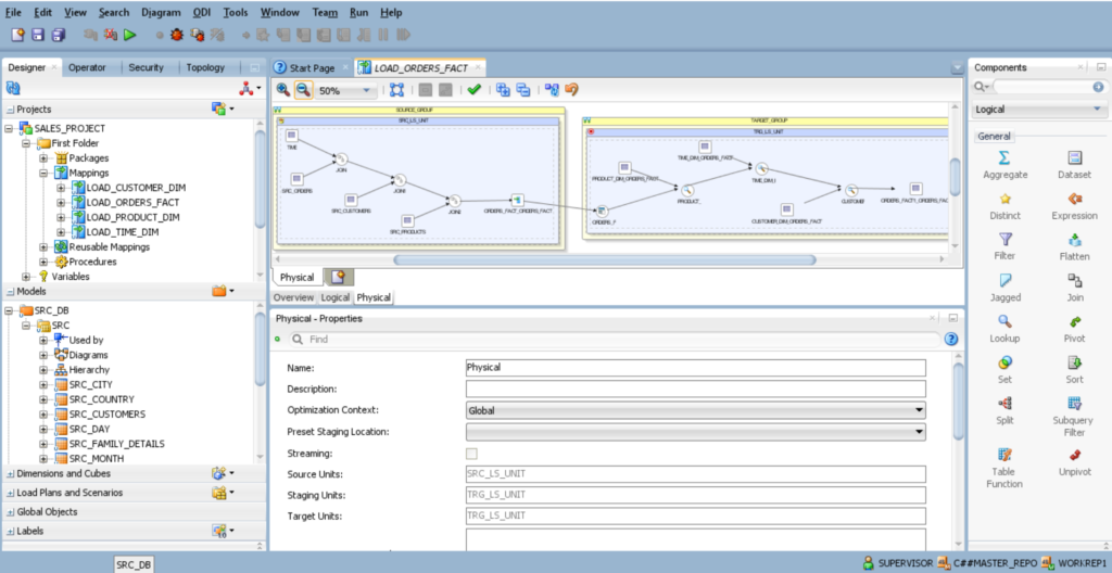
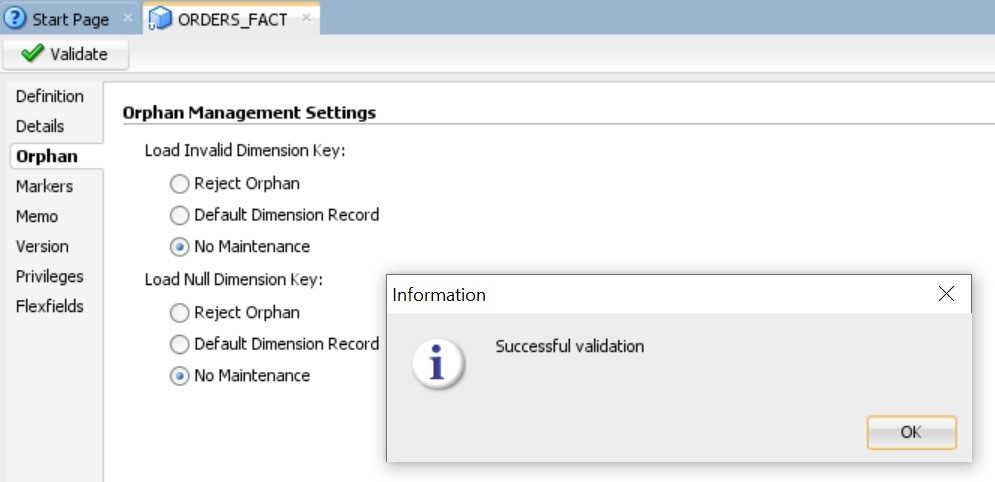
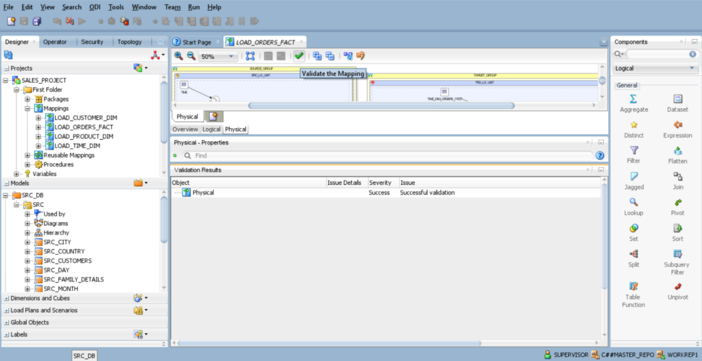
11.Click Validate the Mapping, click Save in the ODI menu bar, and then close the LOAD_ORDERS_FACT.
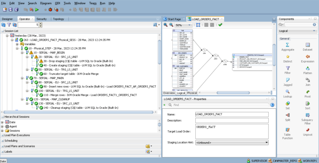
12.Execute the mapping LOAD_ORDERS_FACT.
13.Check result of session task status of the session list in Operator Tab.
14.Now you have to view the data in database TARGET.